The Installation of GN Mud Agitator (F)

GN Mud Agitator plays a very important role in solids control.  To keep both the mud uniform and the suspension of drilling mud, the mud agitator is used to agitate the mud consecutively and reliably. This agitator agitates the mud to make cuttings, silt, and sand pass the solids control system without being precipitated onto the tank bottom.

When installing the GN Mud Agitator (F), it should be lifted horizontally and placed smoothly in the position to be installed.


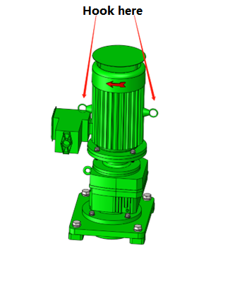
During installation, the agitator should be hoisted horizontally and placed stably at the position to be installed, and then the bottom plate should be fixed on the pad (welded on the tank surface) with an M16×50 bolt assembly.


First of all, it is necessary to check that the four pads of the fixed agitator are in a relatively horizontal position and that the error is within ±1mm, to ensure the normal operation of the equipment. If there is a centralizing sleeve, the centralizing sleeve must be perpendicular to the center of the mounting base.


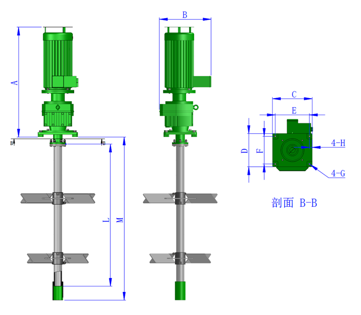
Agitator installation dimension table


Motor

S/C

3Kw 5.5kw 7.5kw 11kw 15kw 18.5kw 22kw
A 772 940 990 1160 1190 1245 1245
B 419 547 507 559 559 589 589
C 390 390 390 430 430 430 430
D 320 320 320 360 360 360 360
E 330 330 330 370 370 370 370
F 260 260 260 300 300 300 300
G φ20 φ20 φ20 φ20 φ20 φ20 φ20
H 30 30 30 30 30 30 30
M Determined according to tank inner depth
L Determined according to tank inner depth

Agitator Mounting Plate

The installation location needs to be determined in advance. Choose the installation location to leave the gap between the impeller and the tank wall. Use a spirit level to maintain the absolute level of the board. Use the adjusting pads to maintain the level and mark the pad’s position.


Stabilizer

All GN agitators are equipped with stabilizers. The total height of the stabilizer is 200mm, install the stabilizer as follows:

The installation of the stabilizer is as follows:

  1. Put a vertical line from the center hole of the mounting base plate, and the point of contact with the tank bottom is the center point of the stabilizer
  2. After determining the installation position of the stabilizer according to the center point, weld the stabilizer sleeve to the bottom of the tank.

3.1.3 Shaft Assembly

After installing the tank bottom stabilizer, put the shaft in the tank for assembly.

  1. Put the shaft into the tank and keep the shaft upright when assembling the impeller and the shaft.
  2. Install the impeller on the mixing shaft.
  3. Put the bottom of the mixing shaft into the welded stabilizer sleeve.
  4. Connect and fasten the rigid coupling reducer end and the mixing shaft end with bolts. At this time, adjust the position of the stabilizer sleeve to make the mixing shaft vertical, and ensure that the mixing shaft rotates normally, and ensure that the stabilizer sleeve will not affect the mixing shaft rotation; otherwise, it will cause the yaw of the impeller shaft, aggravate the wear of the reducer or damage the bearing.
  5. Install the impeller and fix the impeller with bolts.
  6. When the agitator shaft is shipped from the factory, the impeller mounting holes are made according to the tank height offered by the customer.
  7. Spread a thin layer of butter on the bolt and screw it onto the mixing shaft and impeller.
  8. Fix the impeller in the corresponding position on the shaft.
  9. Tighten the bolts gradually and sequentially.
  10. If you need to install the upper impeller, the steps are the same

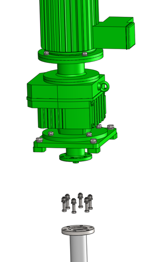
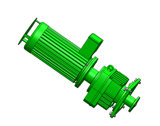
 Motor and Gearbox Assembly and Installation

GN  Solids Control will install the motor and gearbox before delivery.  Clients can install or disassemble as needed. For details, please refer motor/gearbox user manual. Gearbox and Motor Installation drawing please refer figure below.

Gearbox Coupling and Impeller Connection

  1. Align the shaft so that the mixing shaft and the driving shaft coupling are completely connected.
  2. Make sure there is no gap in the outer flange of the coupling. No gap means no connection bias.
  3. Align the coupling, put in and tighten the bolts, and adjust well.

Operation requirements of a disc separator running and shutdown.

It’s very dangerous if the operator didn’t read the manual carefully and violate the steps or regulations to operate a disc separator. Here are the requirements of how to start and stop a disc separator.

2020.12.11 Disc Stack Separator

One. The material entering the disc centrifuge, which must be the lower part of the decanter centrifuge tank, should reach 65°C. It has the advantage of helping to achieve a good separation, minimizing the solid phase in the material, and slowing down the clogging inside the disc centrifuge drum. In addition, it helps to extend the disassembly and cleaning time cycle of the disc centrifuge drum.

Two. The screw pump of the disc separator should be set at a flow rate of 30 cubic meters per hour. The backflow butterfly valve on the screw pump should be open. This is because the disc centrifuge’s material supply line is fitted with a strainer. The strainer barrel will filter out the fibers and oil and mud masses but blind or block the strainer barrel. Especially when the material temperature is lower than 65℃, the oil sludge is more likely to form clumps. The blockage happens when the butterfly valve wasn’t adjusted, the flow meter shows that the flow rate soon becomes smaller; when the butterfly valve was turned a bit down, the flow meter shows that the flow rate soon becomes smaller. This shows that the filter of the strainer is blocked. At this time, the slurry supply pump should be stopped a new filter barrel should be replaced, then restart the slurry supply pump, and turn the flow rate to around 9 cubic meters per hour. The blocked strainer barrel should be cleaned up quickly and installed in time, otherwise, the material supply of the disc separator will be stopped.

Operation requirements of disc separator shutdown.

First. The decanter and the centrifuge must be cleaned inside before shutdown.  The decanter needs to be stopped first, flushed, and then the centrifuge stopped and flushed. This is because, in this system, the decanter centrifuge precedes the disc centrifuge, and flushing water is relatively cleaner water than from the centrifuges.

Two. Close the ball valve of the slurry supply pipe on the inlet of the decanter centrifuge, open the valve on the flushing line of the decanter separator, turn on the flushing pump, and use flushing water for cleaning. Before flushing, lower the drum speed of the decanter to 1500 RPM and set the differential speed to 25 RPM for the best flushing effect. In addition, it is possible to flush twice with two tanks of water, due to the limitation of the water storage capacity of the disc centrifuge tank. Be sure the inside of the decanter centrifuge drum is clean. Then, turn off the pump, close the valve on the flushing pipe, and open the valve on the decanter centrifuge slurry supply pipe.

Three. The disc centrifuge continues to work until the outlet liquid position reaches 600 in the tank. Close the slurry pump, and press the partial slagging button, which will appear to make the slag current spike. You must wait for the slagging current to back down to normal; Press the partial slagging button again, and you also must wait for the slagging current to back down to normal. After that, press full slagging button once, so that the operation will empty internal material out of the disc centrifuge. The irregular operation will cause disc centrifuge motor overload and fault shutdown.

Four. Close the butterfly valve on the filter outlet pipe, open the butterfly valve on the flushing water, and switch on the flushing pump. After the flushing is completed, follow the disc centrifuge shutdown operation requirements, twice partial slagging, once full slagging, then empty the disc centrifuge rotor drum.

Five. Close the valve of the flushing pipe and open the valve on the material line so that its pipeline is in standby mode.

At last, stop the disc separator. When the drum comes to a complete off, stop the pump and turn off the power.

PS. Every day after the use of the fine shaker, use hot water to rinse, and then stop the shaker, and use tools to clean the sieve mesh surface. You must make ensure that the screen surface is clean to prevent the sediment dry on the screen surface, which could be difficult to clean, reduce the separation and spill over slurry to the outlet solid phase.

GN usually provides disk separators with centrifuges together with pumps. Besides, pumps and mud tanks are sometimes necessary. If you want more information, please visit: gnsolidscontrol.com


The Installation and Operation of GN 703 Linear Shaker Screen

The 703 shaker screen is a very popular vibrating screen manufactured by GN Solid Control.

Shaker screen options can be discussed by manufacturer engineers, users, and contractors. The replacement of screens should only be selected by the user.

gnps 703 shale shaker


Changing the screen after use, if the screen mesh is damaged or needs to be replaced.  Remove the wedge, remove the screen, check whether the adhesive strip is enough, then place the new screen on the vibrating table and fix it stably.

Note: When using a shaker screen for the first time, the tension locking should be removed.  The screen mesh could be loose after working, so the operator should always check the mesh of the screen by hammering the wedge.

To adjust, turning the handle wheel near the spring clockwise will increase the angle. While turning the handle wheel counterclockwise will decrease the angle of the deck.

The scroll screen output angle adjustment can be used in both drive and lock modes. When all the mixers have been delivered, the whisk unit is at 0°. When the user uses the vibrating screen according to the characteristics of the drilling mud and the flow rate, the same screen is used, the larger the angle, the better the processing and the higher the processing capacity. As the drilling fluid exits the vibrating table, increasing the angle of the platform prevents the drilling fluid from migrating.

GNPS703 can adapt to different meshes. Generally, when the vibrating screen is the first step of separation equipment, the vibrating screen can be 30-100 meshes. When the shaker is part of the sludge remover, the screen can shake 80-200 mesh. This equipment can use 10-200 mesh screens.

In order to simplify the installation and removal of the screen, the GNPS703 has developed a quick installation process. The construction is a special type that uses tension wedges to hold the screen in place.  The structure consists of stand rods and wedges. When installing the screen for the first time, we need to check the size of the screen, for example, 1250±2mm, the tolerance should not exceed that. After the rubber slide is fixed, install the screen and stand behind the sliding screen (drilling fluid suction) and drive the wedges evenly on both sides, and push or tighten the wedges with a hammer to make both sides flat. level. Re-tension each screen.

The low density liquid separated from the shaker could pumped into a centrifuge for second separation.

How do you think that GN shaker screen has a good design?

shale shaker is a screen mesh or a sieve that vibrates. The vibrating shaker screen mesh strains the slurry and liquid out of the mud. This mud is further sent to the mud tank. When the drilling equipment processes finer cuttings, they can usually be collected and recycled by a shale shaker.

The different need for a shale shaker screen is based on different mesh sizes and could be adjusted following the various API mesh number standards.

Mesh size usually is connected with the mesh number (a US measurement standard) and its relationship to the size of the openings in the screen and the size of particles that could pass through the openings. It is very easy to figure out the mesh number. All you need to do is count the number of openings in one linear inch of screen. This count is called the mesh number. A 4-mesh screen mesh means there are four small square openings across 1 inch of the screen. A 100-mesh screen means 100 openings per inch, and so on.

GN Solids Control manufactures shale shakers and screen meshes in the oil and gas industry. We provide API standards shale shaker screens for solids control shakers and mining shakers. GN shale shaker screens are compliant with API RP 13C.

What API Size Shaker Screen is available from GN?

D 100 Separation(Micron) API Screen Number
>1850.0 TO 2180.0 API 10
>780.0 TO 925.0 API 20
> 462.5 TO 550.0 API 35
> 390.0 TO 462.5 API 40
> 275.0 TO 327.5 API 50
> 231.0 TO 275.0 API 60
> 196.0 TO 231.0 API 70
> 165.0 TO 196.0 API 80
> 137.5 TO 165.0 API 100
> 116.5 TO 137.5 API 120
> 98.0 TO 116.5 API 140
> 82.5 TO 98.0 API 170
> 69.0 TO 82.5 API 200
> 58.0 TO 69.0 API 230
> 49.0 TO 58.0 API 270
> 41.5 TO 49.0 API 325


How many types of shaker screens does GN have?

According to the factory stock, there are at least 3 kinds of screens: flat stainless-steel screen, wave stainless screen, and Polyurethane sieve plate. We don’t use API to describe a sieve plate. But Polyurethane sieve plates are also widely used in exploring industries.

Now, GN is able to provide replacement screens for nearly all widely known international shale shaker brands in the drilling industry.

1. GN uses robots to weld the internal steel frame to ensure consistency.
2. GN has its 3-layer design of API 60, while other suppliers in China use API 120.
3. The outer plastic material is 100% new and clean, not recycled materials.
4. The wire mesh is pre-tensioned so that the surface of the screen is stronger.
5. GN screen can be repaired with a screen rubber stopper when the damage is less than 10% of screen mesh.

All in all, GN screen meshes are well-designed and welcomed around the world. If you have a solids dewatering project and need replacement screens, don’t miss GN Solids Control!

GN DECANTER CENTRIFUGE FOR CORE AND DIAMOND DRILLING APPLICATIONS


GN Solids America is committed to protecting the environment and complying with environmental discharge regulations. Especially in drilling fluid recycling applications, GN solids control equipment could maximize the recovery of drilling cuttings and recover fluids. GN small decanter centrifuge is mainly used in diamond drilling and core industry to remove fine solids in fluids.


The GN decanter centrifuge combined with other solids control units forms a complete dewatering system. At the remote drilling site, our dewatering system allows drilling contractors to reduce the amount of wastewater and water transported. The complete dewatering system can fully recycle contaminated drilling fluids and recover clean water. The Vibratory Screen functions as the first stage to launch large, aggressive particles. The GN decanter centrifuge is normally installed at the end of the dewatering system to remove fine solids and obtain clean fluids. Here are some reasons why many drilling companies choose the GN centrifuge. Small Decanter Centrifuge

Advantages of GN Small Bowl Centrifuge


  1. GN core and diamond drilling decanter centrifuge is a 9” bowl centrifuge that occupies a very small size and fits the restricted drilling site.


  1. 3800RPM is capable of removing 2~5 micron solids in fluids. We also offer Fixed Speed ​​Control Panel, Variable Frequency Drive(VFD) Control Panel, Standard Motor and Hydraulic Motor to meet or exceed customer expectations.


  1. We use high-standard duplex stainless steel to manufacture the centrifuge, and high-quality and durable bearings are also installed in the decanter centrifuge.


  1. The GN centrifuge can efficiently remove finer solids and control the weight or density of fluids, thus obviously improving ROP.


Except for drilling and diamond applications, GN centrifuges are also used in oil and gas drilling fluid industry. We have 14″, 18″ and 22″ bowl centrifuges to meet different requirements. Contact GN for more information.

SOLIDS REMOVAL UNIT FOR THE MINING INDUSTRY

The GN Compact Solids Removal Unit (SRU) is used for solids control of drilling fluids for small mining rigs for diamond drilling. Instead of using traditional drilling sumps, the GN Solids Removal Unit is described The GN Solids Removal Unit (SRU) is used for solids control of drilling fluids for small mining rigs for diamond drilling. Instead of using traditional drilling sumps, drilling contractors and resource companies in the drilling industry describe the GN Solids Extraction Unit as the way of the future. The closed loop drilling fluid system is a cost-effective solution to reduce environmental impact and greatly improve the efficiency of drilling operations.

Working principle of the GN solids removal unit

Drilling fluid circulates directly from the drill collar to the GN Mini Shale agitator for first-stage solids removal. And a positive displacement feed pump carries drilling fluids below the agitator tank to feed the GN mini decanter centrifuge for fine solids removal. Clean drilling fluids are returned to the drilling hole for reuse. The highly mobile unit also incorporates a mixing chamber and mixing hopper and pumps, allowing chemical drilling fluids to be added accurately and efficiently. The GNLW223 Baby Centrifuge is the world’s smallest decanter centrifuge for treating drilling fluids. It is popular in the diamond core drilling industry.


Features and Benefits of the GN Solids Removal Unit

Process capacity: 0-150 LPM

Reduction of drilling fluid consumption by more than 40% Autonomous unit with agitator, centrifuge, pumps, mixing, tanks and generators (optional).

Environmentally friendly, no drilling of wells: reduced water consumption

Reduces site installation and repair costs

Reduced downhole rig costs by improving diamond drill bit/rod life.

CENTRIFUGE FOR FRUIT AND VEGETABLE JUICE

GN Solids Control manufactures the decanter centrifuge for the profitable production of fruit juice, direct juice, and vegetable juice. The high-quality machine is designed to achieve high production output with lower costs due to reliable operation, lower maintenance, and service cost. GN has developed other lines of processes in which it diversifies its processes to the one it has been working on normally directed at solids control equipment.

Typical fruit and vegetable juice process

  • The vegetable or fruit is fed to a mill by means of an elevator for grinding.
  • The belt press is washed with water and separates the fluid into a liquid phase and solid phase.
  • The solid phase is sent to the vibrating screen and the liquid phase is sent for enzymatic treatment.

After treatment, the liquid phase is sent to a decanter centrifuge to produce fruit or vegetable juice.

However, among the above processes, many other treatments and processes are involved to meet the quality and standard for beverage manufacturing.

Advantage of GN Decanter Centrifuge to produce fruit juice and vegetable juice:

  • Optimize juice extraction to maximize the yield of fruit juice and vegetable juice.
  • Reduction of the content of settleable solids and improvement of the quality of the juice generate more benefits for the producer.
  • Optimum clarification of fruit juices, and vegetable juices with a reliable machine with lower maintenance and operation costs.
  • High-efficiency Decanter Centrifuge and beverage-making machine to adapt to different plants.
  • Worldwide distribution partners in the juice manufacturing industry.
  • High-quality stainless steel is made from centrifugal casting for durability and long life.
  • Less space, clear design, easy access, and less maintenance to minimize the cost of installation and operation.

Popular fruit juices include orange juice, grapefruit juice, strawberry juice, apple juice, grape juice, pear juice, mango juice, peach juice, apricot juice, kiwi juice, hawthorn juice, pineapple juice, guava juice, passionflower juice, tomato juice, fresh carrot juice, etc.

Popular vegetable juices include fresh carrot juice, celery juice

cabbage juice, cucumber juice, tomato juice, and pumpkin juice with honey. Normally, vegetable juice is a juice made from all kinds of vegetables.

The functionality that GN offers in its centrifugal decanters in its wide range of models allows preventive maintenance to be carried out over longer periods and with less economic impact, allowing the end customer to maximize their production costs; Seeing GN Solids control equipment as the best option, a safe and guaranteed investment in the short and long term.

GN SOLIDS CONTROL SHIPS EXPLOSION PROOF CONTROL ENCLOSURE TO CUSTOMER


GN Solids Control manufactures a complete line of equipment for the control, separation and transport of solids, including decanter centrifuges (2-phase and 3-phase), disc separators, shale shakers, screw filter presses, etc. Much of the equipment needs the explosion-proof capability to be able to work in hazardous operating conditions.

Due to this requirement, GN Solids Control manufactures blast control panels for the applications. A typical application is the decanter centrifuge in oil and gas drilling.

For such an application, GN Solids Control provides an air-conditioned control panel. This type of control panel can work up to 55 degrees Celsius.

This type of panel uses an airtight, corrosion-resistant stainless steel casing. Compressed air is fed into the control panel to establish a positive pressure so that the explosive gas cannot enter the control panel and thus an explosion does not occur.

Inside this control panel are all the control elements. The most important is the PLC.

GN Solids Control standardized PLC, uses Omron or Siemens, and is moving to use only Siemens PLCs and touch screens.

The control panel also houses the VFD. Due to the high power of VFDs, it is necessary to use a large enclosure. Good ventilation is imperative for such an application.

The advanced control program is used in the said control panel. It will control the decanter centrifuge, it will automatically and continuously optimize the parameters of the decanter centrifuge so that it always works in optimal conditions according to the predefined target. It also monitors the temperature and vibration of decanter centrifuges to protect your safety. GN Solids Control also provides an optional monitoring kit to provide real-time analysis of bearings and alerts once anomalies are found by the PLC through its advanced algorithm.

The GN Solids Control Dashboard also provides other functionality please contact GN Solids Control for more information.

GN MINING SLUDGE TREATMENT SYSTEM


GN Solids Control has within its line of development the manufacture of complete mining sludge treatment systems for clients in the mining industry. As a leading manufacturer of solids control equipment and waste management treatment systems, GN Solids Control has provided products to more than 70 countries.

In the mining area, some customers use high-pressure water to wash minerals, because those finer particles are also very expensive, they also need to recycle small particles. This GN mining sludge treatment system is used to recycle expensive particles. It mainly includes the following three parts:

1. GN High G-Force Vibratory Screen

A vibrating shaker is one of the most used treatment equipment for the separation of solids and liquids. Using the high G-force (up to 8.0 G), the slurry separates on the shale shaker screens due to gravity differences between the solid and liquid. GN Solids Control manufactures thousands of vibrating screens each month. Many replacement screens are used on Mi-Swaco, Derrick, NOV, FSI and Kemtron shale shakers.

2. GN decanter centrifuge

The GN centrifuge is the second stage of treatment. After treatment with a GN Hi-G agitator, solids larger than 100 microns can be separated, while smaller solids or particles need to be further treated using 10-inch or 4-inch GN cyclones. Sometimes GN decanter centrifuges are directly used to separate the particles larger than 2~5 microns. Here GN recommends using an 18-inch rotary bowl centrifuge, which is GNW452. GN centrifuges are widely used in various areas, many big customers like Shell, Baker Hughes or Bariod are using GN centrifuges.

3. GN mud tank

The GN Hi-G agitator and centrifuge are mounted in the mud tank. And there is also a screw feed pump (feed decanter centrifuge) fixed on the side tank.

With this compact design, the GN mining sludge treatment system can be easily moved between different sites.

BIOFUELS INDUSTRY


Biofuel is a clean and renewable energy source. It is a renewable diesel fuel made from oil crops, wild oil plants, aquatic plant oils such as engineered microalgae, animal oils, food craving oil, and other raw materials through the process of transesterification. It is a high-quality substitute for petroleum and diesel, also known as “renewable oil”. The supply of biofuels is not controlled by OPEC, it is not restricted by mineral reserves, and it is cheap and stable. It plays an important role in the process of improving national energy security and environmental protection. Biofuel is a typical “green energy”. Developing biofuels is of great strategic importance for sustainable economic development, promoting energy substitution, reducing environmental pressure, and controlling urban air pollution. The GN decanter centrifuge and disc separator play an irreplaceable role in the biofuel processing process. It can be used not only for solid-liquid separation but also for liquid phase clarification and liquid-liquid separation of different densities, so as to obtain better biofuel and meet fuel requirements by indicators.


GN 2 and 3 phase decanter centrifuge:

  • GN has a 2-phase decanter centrifuge and a 3-phase decanter centrifuge, which can be applied to different process targets in biofuel production. GN 3-phase decanter centrifuge is commonly used to process the raw materials before 3-phase esterification and separation of free fatty acids, glycerol, and salt precipitates (such as potassium sulfate in glycerol treatment). The 2-stage decanter centrifuge is often used to re-wash salt precipitates, such as the separation of potassium sulfate produced in glycerol treatment.


GN 2 and 3 phase separating disc:

  • GN has a 2-stage disc stack separator and a 3-stage disc stack separator. The 2-phase disc stack separator is mainly used to clarify solids in the liquid phase, while the 3-phase disc stack separators can separate liquids with different densities, at the same time discharging the solid residue. In the biofuel production process, a three-stage disc stack separator is generally used to separate glycerin water from fatty acid esters and biodiesel washing. 2-stage clarifier disc stack separators are used to separate solid impurities from biofuel. Compared with the decanter centrifuge, the advantage of the disc stack separator is that the separated biofuel is cleaner and more complete. The disadvantage is that it is not suitable for high solids materials or materials with very large particles. Therefore, the decanter centrifuge and the disc stack separator are often used in the processes before and after biofuel production to achieve the optimal comprehensive goal.

COMMON APPLICATION OF THE BIOFUELS INDUSTRY:


Fuel ethanol processing technology: corn/cassava, milling, saccharification, hydrolase, fermentation, crude distillation (fuel ethanol), distiller’s grains, separation and dehydration (distiller’s grains as feed), fine distillation, condensation, fuel ethanol. In the separation and dehydration process, the GN C series high-speed decanter centrifuge is used to dehydrate distiller grains after crude distillation. C series high-speed decanter centrifuges are more comprehensive in separating and dehydrating distiller grains after crude distillation, with low residue alcohol content and high alcohol recovery. At the same time, the energy consumption of the follow-drying slag is low, which saves costs. In the biofuel processing process, the GN disc stack separator is abundantly used in methyl ester, glycerin, catalyst, soap removal, methanol, water washing methyl ester, fatty acid extraction, glycerin field desalination, and others.